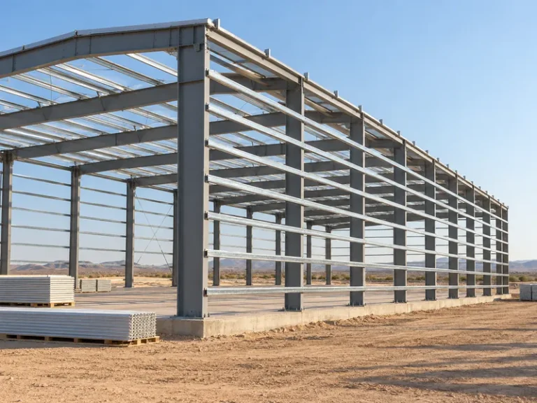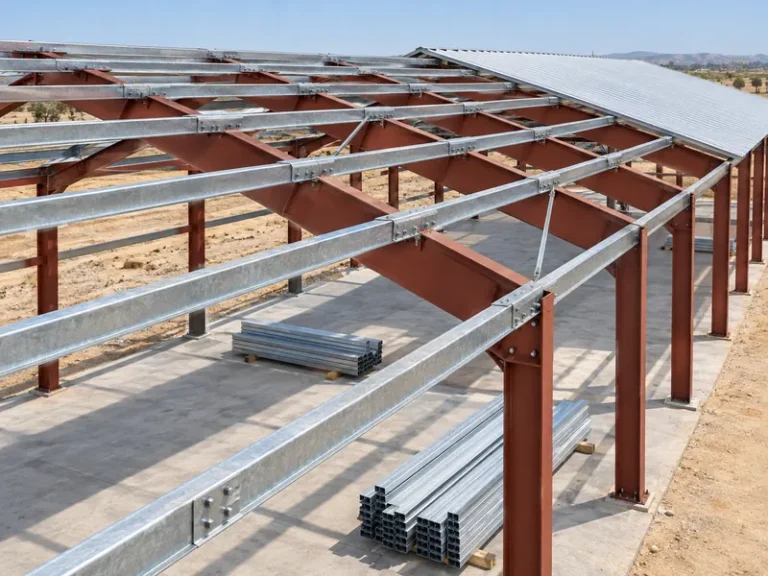
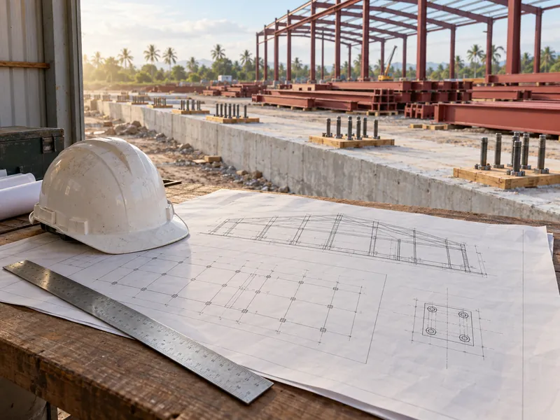
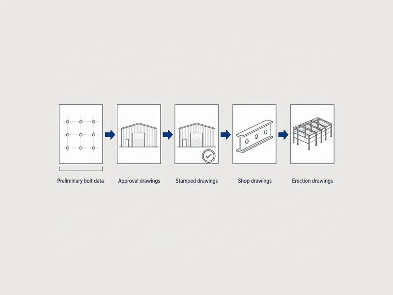
Pre engineered metal building drawings arrive in stages, and each stage needs its own handover check. At the approval stage, the buyer checks dimensions, openings and scope. The anchor bolt plan and column reactions need a check before they go to the foundation designer. The erection drawings need a cross-check against the foundation drawings before steel reaches site. The drawing set is where pre engineered metal building architecture becomes numbered sheets that fabricators, foundation designers and erectors each work from. The risk at every handover is that one party works from a sheet issued for a different purpose.
The checks below are aimed at owners’ project managers, EPC contractors and procurement teams on industrial and commercial steel buildings. They cover what each drawing set is for and which data must move between parties. Foundation calculations, erection methods and the permit procedure of any specific country are outside this scope; those depend on the project contract and local requirements. Steel structure building drawing handovers need the approval, anchor-bolt and erection sets kept distinct.
Crane data, where required, belongs in the coordinated drawing package for industrial buildings. Door openings also need to agree across the sets for aircraft hangars.
Check the specified envelope interfaces for cold storage buildings through that same handover sequence.
Which Drawing Sets Arrive on a PEMB Project
A PEMB project usually produces several drawing sets at different points. Read each set by what it is allowed to do. A quote-stage bolt pattern, an approval set and an erection set can show the same frame lines, yet only some of them are meant to support concrete work or field assembly. Knowing the purpose of each set before it arrives keeps the team from building on data that was only meant for review or budgeting.
| Drawing set | What it is for | What the receiving team does | What it should not be used for |
|---|---|---|---|
| Preliminary anchor bolt pattern and estimated reactions | Early estimating and budgeting | Use for cost planning and early foundation sizing discussions | Designing the foundation or setting anchor bolts |
| Approval drawings | Buyer review of the building as ordered | Check dimensions, openings, accessories and scope; mark changes; confirm stamp status with the supplier | Assuming the design is final before sign-off |
| Stamped or permit drawings, where the project requires them | Engineering record and authority review | Confirm who sealed the set, what it covers and whether any review comments are pending | Assuming the seal covers the foundation |
| Shop (fabrication) drawings | Telling the factory how each piece is cut, drilled and assembled | Request a copy where the contract provides for shop drawing review | Field assembly |
| Erection drawings | Showing where each member goes on site, with piece marks | Cross-check against the anchor bolt plan and foundation drawings before field work | Replacing the foundation drawings |
Names and the number of stages vary between suppliers, so the table describes functions; the titles printed on the sheets will differ. One supplier may combine the approval and permit stages; another may issue the anchor bolt plan inside the main set as part of the frame drawings. What matters at each handover is the question in the third column: what does the receiving team need to verify before it acts on this sheet?
Pre Engineered Metal Building Details to Check on Approval Drawings
Approval drawings are the buyer’s chance to confirm that the building on paper matches the building that was ordered. The review therefore centres on dimensions, openings and supply scope; structural design belongs to a separate check. The set is a detailed picture of the order: overall dimensions, frame lines, door and window positions, and accessories. Opening locations deserve the most attention. A door moved by one bay after sign-off can change the wall framing and bracing layout behind it. The system choice behind that drawing package is compared in pre engineered metal buildings vs conventional steel buildings. Interior column lines shown on these drawings follow the choice explained in clear span vs multi span metal building.
A practical review compares the drawings line by line against the purchase contract and the agreed scope of supply. Items that often need confirmation include:
- overall dimensions, clear height targets and frame spacing against the site layout;
- every framed opening, including size, location and the wall it sits in;
- metal building eave details and gutter arrangements against the wall and roof panels ordered;
- accessories, liner panels, insulation and trims that the contract says are included.
Whether the approval set carries an engineer’s stamp has to be confirmed, never assumed. At least one supplier states in its published glossary that its approval drawings are not sealed by an engineer, and practice differs between suppliers and contracts. Before signing, the buyer should ask the supplier whether the approval set is stamped and, if so, what the stamp covers.
Sign-off timing also depends on what the project still has open. Where the project needs authority review, the team should check whether any pending comments could change the drawings before the supplier releases the building for fabrication. Signing early saves calendar time only if nothing that affects the frame is still unresolved.
Metal Building Framing Details and the Design Loads Printed on Them
The load notes on the framing drawings show what the frame was designed for. The buyer’s job is to confirm that those values match the loads the project actually requires. Supplier drawings print design values such as wind speed and ground snow load near the load notes. A trade article in the U.S. structural engineering press warns that on catalog-type buildings these can be catalog values, not site values. For that reason, a reviewer compares them first against the governing load standard. The guide to metal building design loads explains how the loads on approval drawings relate to the order inputs.
An engineer’s stamp does not by itself prove that the printed loads suit the site. Stamped metal building engineered plans show that a registered engineer took responsibility for the design under the loads listed on the drawings. The load inputs themselves come from the project side. For projects outside the United States, those inputs come from the local code and the project’s own design brief, and local requirements and the contract decide who reviews them.
Three checks on the framing sheets cover the load questions a buyer can verify from the drawings:
- Compare every design value in the load notes, including wind, snow where relevant, seismic and any collateral load, against the project’s written design criteria.
- Confirm in the contract, the general notes and the title block who sealed the drawings and which members and documents the seal covers.
- List any equipment the building will carry, such as cranes, hoists, mezzanines or heavy roof-mounted units, and confirm it appears in the design.
Equipment added after approval leads straight to redrawn steel building details. Lifts, hoists and future mezzanines added after the fact sit outside the original stamped scope. In a steel structure workshop design, a crane still “to be decided” at approval stage is a reason to hold sign-off until the crane is defined. Signing first and revising later sends the frame back for redesign.
Metal Building Foundation Plan vs the Anchor Bolt Plan
The anchor bolt plan tells the foundation designer where the building attaches. The metal building foundation plan is a separate design that someone else usually produces. An anchor bolt plan is a plan-view drawing that gives the diameter, location and projection of each anchor bolt. It may also show column reactions, with magnitude and direction, and maximum base plate dimensions.
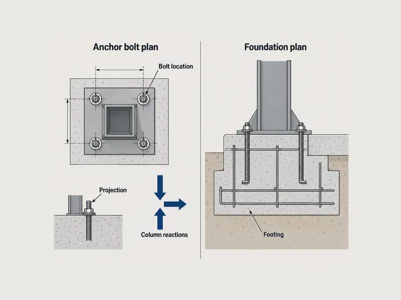
Footing sizes, reinforcement, embedment and slab design are not part of the anchor bolt plan. Published guidance from the metal building trade press is consistent on this point: the manufacturer’s engineers do not design the foundation. The same guidance says the foundation almost always needs its own design instead of a copy of a catalog detail. It places soil bearing capacity and slab thickness among the site-specific items outside the steel package.
A contract can still move foundation design to the steel side. It may assign that work to the steel supplier or to a design partner under the same agreement. When it does, the parties should write the split of responsibility into the contract and the drawing list, so that nobody assumes the anchor bolt plan is doing the foundation’s job.
Column reactions link the two drawings. Supplier drawings typically tabulate base reactions by column line, giving vertical, horizontal and uplift components. The foundation designer uses them to size footings and anchorage. Once the supplier issues a quote, it can provide a preliminary bolt pattern with estimated reactions, but that information is for estimating and budgeting only.
A Four-Step Handoff From Anchor Bolt Plan to Foundation Design
Once the anchor bolt plan arrives, the project team should confirm four things before passing it to the foundation designer and scheduling the bolt setting. The steps combine what published supplier glossaries and trade articles say each document contains and how to reconcile the documents. They are a verification method, not a substitute for the foundation engineer’s design.
- Anchor bolt data. Check that every column line has bolt diameter, location and projection, and note whether the plan gives maximum base plate dimensions the foundation must accommodate.
- Reactions by column line. Confirm the vertical, horizontal and uplift reactions for each column line. Confirm also that the values come from the current design and that it has replaced the preliminary estimate issued at quote stage.
- Foundation documents beyond the bolt plan. Confirm which party is producing the foundation plan, footing details and embedment requirements, and that this party has the reactions and bolt data in hand.
- Cross-check and current revision. Compare the anchor bolt plan, the erection drawings and the foundation drawings for grid lines, column positions and bolt patterns. Then get confirmation from the supplier and the foundation designer that the revision in hand is the one cleared for this pour.
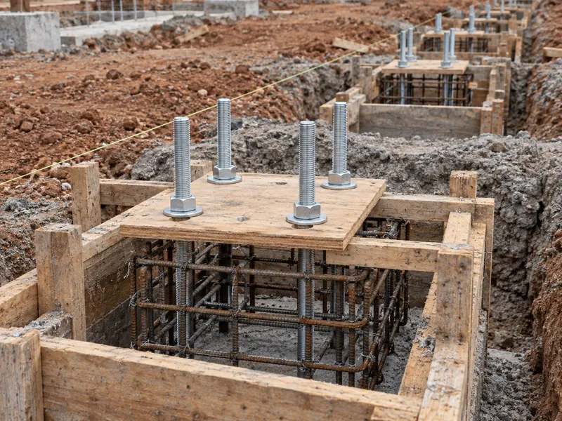
The order matters because concrete cannot be revised. A bolt pattern that is wrong on paper is a drawing revision. A bolt found in the wrong place after the concrete has set is a site repair, and a far more expensive one. Building from preliminary bolt data invites that outcome, especially when openings or frame spacing changed during approval. The handoff steps tell the team which questions to ask; the contract and local rules decide who answers them and which document status permits construction.
Erection Drawings, Revisions and Sheet Matching
Erection drawings guide assembly on site and work alongside the foundation drawings, which they do not replace. Each erection sheet shows where members are installed, with piece marks that identify each member. Shop drawings are a different set: they tell the factory how each piece is cut and drilled. The foundation drawings and their designer still govern the foundation, anchorage and slab.
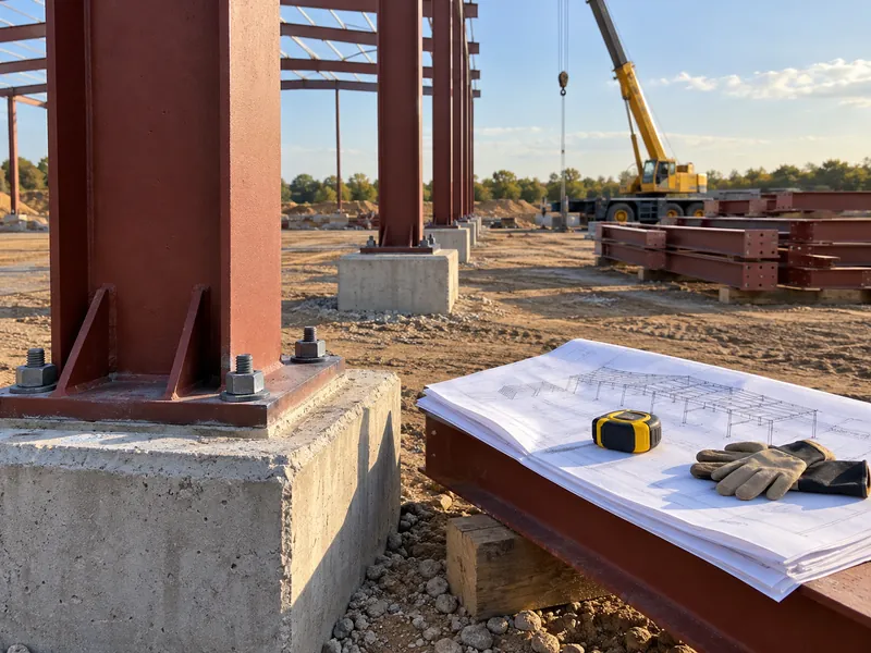
Sheets drift apart through revisions. Each change made during approval, such as a moved opening, an added canopy or a crane added late, can produce new framing sheets, a new anchor bolt plan and new reactions. Before the erection set goes to the crew, the project team should confirm that every sheet in hand carries the latest revision. The foundation designer should also bring the foundation drawings up to the same revision of the bolt plan.
A short sheet-matching routine turns those revision checks into a field-set review:
- grid lines and column numbering identical across the anchor bolt plan, erection drawings and foundation plan;
- piece marks on the erection drawings matching the delivery documents;
- revision numbers and dates recorded for every sheet issued to site;
- any sheet with a preliminary or review status identified, with written confirmation from the contract-assigned responsible parties before anyone relies on it for the relevant field activity.
A status label on metal building drawings does not by itself settle whether a sheet can be used. One trade article describes preliminary anchor bolt data marked as not for construction, but status labels and their meaning differ between suppliers. The reliable test is a written confirmation from the responsible parties that a given revision is the one approved for construction on this project.
The Check That Protects the Foundation Pour
The handover between the anchor bolt plan and the foundation pour is a high-consequence step, because it is the point where a drawing error becomes cast concrete. Up to that point, the team can correct approval comments, framing changes and late equipment on paper. Once the bolts are in the concrete, every mismatch becomes a site repair. Settle openings and equipment on the approval drawings first, and confirm that the reactions and bolt data come from the current design. Then have the supplier and the foundation designer agree on the same revision before anyone sets a template on the formwork.
FAQ
Can anchor bolts be cast before the final drawings are issued?
Do not cast anchor bolts from preliminary data. A quote-stage bolt pattern can change once openings, frame spacing or equipment are settled at approval. Wait for the anchor bolt plan of the approved design, and for the foundation designer to confirm that the foundation drawings match that revision.
If the steel drawings are stamped, is a separate foundation design still needed?
A separate foundation design is still needed in most cases. The stamp on the supplier’s drawings relates to the steel building design under the listed loads. Footings, embedment and slab depend on site soil, so the foundation designer handles them separately. The exception is a contract that explicitly assigns foundation design to the supplier or its design partner.
What should be checked on approval drawings before signing them off?
Approval drawings should be checked against the contract for dimensions, frame spacing, openings, accessories and supply scope. Two open questions also belong in the sign-off: whether the set is stamped and what any stamp covers, and whether planned equipment loads are already in the design.
Do new drawings come out if a crane or mezzanine is added after approval?
Adding a crane, hoist or mezzanine after approval means a redesign and new drawings. The added loads can change the column reactions, so the revised reactions and anchor bolt data must reach the foundation designer before the pour.
Who resolves a mismatch between the anchor bolt plan and the foundation drawings?
The steel supplier and the foundation designer resolve it together, under the responsibility split set by the contract. The supplier confirms the bolt pattern and reactions for the current design; the foundation designer confirms the foundation matches them. Raise the mismatch before the pour, while a revision is still a drawing change and not yet a site repair.
Further Reading
- Design Resources | MBMA: The Metal Building Manufacturers Association’s list of its Metal Building Systems Manual, inspection guide and performance guide specification, useful when writing the project design criteria that the load notes on supplier drawings should match.
- eTools: Steel Erection, Metal Buildings | OSHA: The U.S. Occupational Safety and Health Administration’s summary of erection rules for systems-engineered metal buildings, including minimum anchor bolts per column and rigid-frame bolting before hoist release; it is a U.S. federal rule, so projects elsewhere should check the local equivalent.