
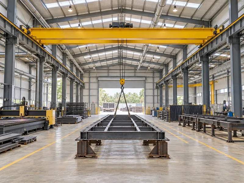
Steel workshop crane requirements are easiest to get right when they start from the shop floor: where material arrives, where it is processed and assembled, and where it leaves. Those pick-and-place points decide how much of the floor the hook must reach and how high it must lift. Coverage and clearance then become the span, column spacing, rail elevation and load inputs that a steel frame structure workshop is designed around. This article sets out that planning order. It does not cover load factors, deflection limits, member sizes or prices. The final structural, electrical and civil design remains with the project’s locally qualified engineers.
Why Rated Capacity Alone Does Not Set Workshop Crane Requirements
A request for “a 10-ton crane” leaves most of the structural questions open, because rated capacity is only one of the loads the workshop frame has to carry. The building also carries the crane’s own weight, the trolley and hoist, and the dynamic and impact effects of lifting, lowering, accelerating and braking. Columns take vertical loads from the runway. They also take horizontal loads from bridge travel, trolley movement and load swing. Self-weight and these forces change with the crane configuration, so the crane supplier’s data should drive the frame design, not the nameplate tonnage alone.
Duty class is a second variable that capacity cannot answer on its own. Lift frequency, travel distance and how close typical loads come to the rated capacity all affect the service class the crane is built for. CMAA, for example, uses six service classes, from Class A (standby or infrequent service) to Class F (continuous severe service). CMAA is one classification system, and a project may specify another. The owner, crane supplier and engineer should agree early which system applies. Record the expected lifts per shift and typical load weights alongside the class letter.
Local supply voltage and frequency belong in the same early inputs: record them for the site and share them with the crane supplier.
Map Pick-and-Place Points Before Fixing the Crane Bay
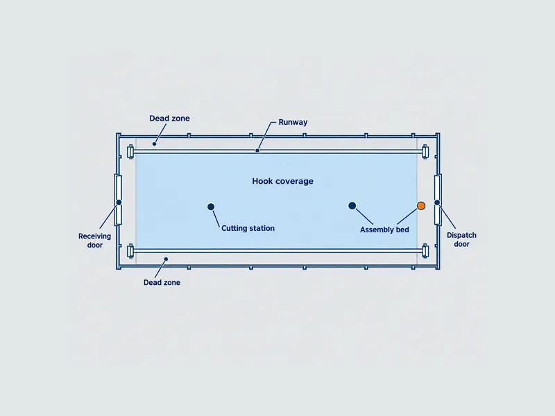
Size the crane bay to reach the places where loads are actually picked up and set down, not to the building footprint drawn first. A workshop laid out for steel fabrication, equipment assembly or maintenance has fixed points such as the receiving door, cutting or machining stations, assembly beds, test areas and the dispatch door. If any of those points sits outside the hook’s reach, the crane cannot serve it no matter how much capacity it has.
A practical mapping sequence on the workshop layout looks like this:
- Mark every pick-up and set-down point, with the heaviest and the bulkiest load expected at each one.
- Draw the coverage area the hook must reach, including the ends of the runway and the strips along each side wall.
- Ask the crane supplier for the hook approach limits of the proposed crane configuration: how close the hook can get to the runway ends and to each side.
- Overlay those limits on the plan and highlight any pick point that falls in a dead zone.
- Decide whether to move the process station, extend the runway, widen the span or accept a secondary lifting method for that point.
Hook approach is easy to overlook until the layout is fixed. The hook cannot reach all the way to the rails or the runway ends. The remaining distance depends on the crane design, so only the supplier can confirm it. A machine placed tight against the end wall may then need a longer runway or a different station position. That choice is easier to make on paper than after the columns are set.
Turn Lifting Height and Overhead Obstructions Into Clearance Inputs
The tallest lift in the process sets the required hook height, not a standard eave height. Start from the highest point a load must clear, such as a machine lifted over another machine, a fabricated frame turned upright or a part loaded onto a truck bed. Add the sling or lifting-attachment length below the hook. That figure is the planning input the crane supplier uses to work out how much space the hoist, trolley and bridge need above it.
Overhead obstructions then set the upper boundary. Depending on the building, these may include roof purlins and bracing, ventilation ducts, lighting, cable trays, piping and fire-protection lines. Place each one on the section drawing at its planned elevation so that the crane envelope and the services do not compete for the same space. The US OSHA rule for overhead and gantry cranes, 29 CFR 1910.179, gives one reference point. It requires a minimum clearance of 3 inches (about 76 mm) overhead and 2 inches (about 51 mm) laterally between the crane and obstructions. Projects outside the United States should confirm the equivalent requirement under local regulations.
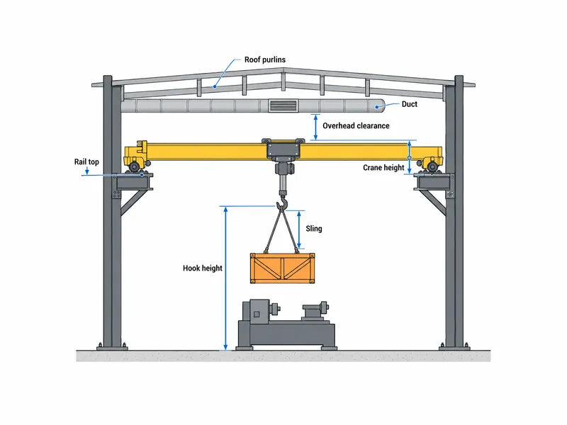
The same hook height can call for different building heights, depending on the crane configuration. Where vertical space is limited, suppliers can sometimes use a trolley or hoist arrangement that sits lower relative to the girder. That arrangement can recover hook height without raising the roof. Whether it fits depends on the capacity, span and duty, so share the clearance section with the crane supplier before fixing the eave height.
Convert Crane Coverage Into Structural Inputs for the Workshop Frame
With coverage and clearance agreed, each planning result feeds a structural input. The table links each input to the planning step it comes from. It is a planning aid only. Final values are confirmed with the crane supplier and the project’s local structural engineer, and responsibilities belong in the project documents.
| Structural input | Comes from |
|---|---|
| Crane span and building span | Coverage area across the bay, minus hook approach at each side |
| Runway length and column spacing | Coverage along the bay, hook approach at the ends, door and station positions |
| Rail top and bracket elevation | Required hook height plus the crane’s own height and overhead clearance |
| Wheel loads and horizontal forces | Crane capacity, self-weight, configuration and duty |
| Runway support type | Column capacity, wheel loads, available floor space |
No row in the table can be finalised from the building side alone, because each value depends on the crane configuration chosen.
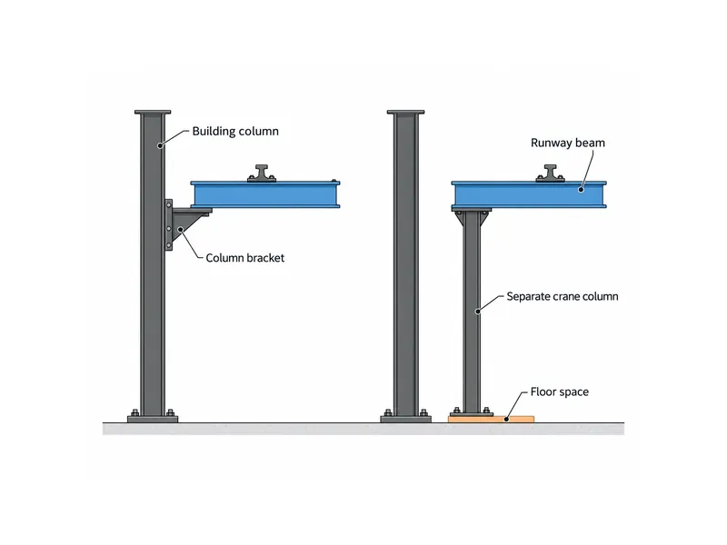
Runway support is a structural decision with layout consequences. Runway beams can sit on brackets or corbels attached to the building columns, or on separate crane columns that do not rely on the building frame. Bracket support depends on the main columns having capacity for the crane’s vertical and horizontal forces, which the structural engineer checks against the supplier’s wheel loads. Separate columns occupy floor space along the walls. Either way, the choice affects where stations can sit along the side walls, so make it before the layout is frozen.
Forces along the runway need a defined path as well. Crane braking and acceleration act along the runway line, and the structural engineer decides how the frame resists them. Runway end stops belong to the same system, because the crane has to be stopped safely at the limits of travel.
Extra Checks When a Crane Goes Into an Existing Steel Workshop
Before any crane is specified for an existing workshop, its capacity has to be checked, because the building may never have been designed for crane loads. The starting documents are the original structural drawings, steel calculations, column details and foundation design. If those are missing, the engineer may need a site survey before anyone discusses crane size.
The main checks for an existing building are:
- Original design loads, to confirm whether crane loads were included at all.
- Column capacity for added vertical loads and horizontal forces at runway level.
- Foundation design, checked against the added column loads.
- Corbels, brackets and embedded plates, re-measured on site for their actual positions and elevations against the drawings.
The engineer uses the drawings and the site measurements together to decide whether the runway can use the existing supports, and how to fix it if so.
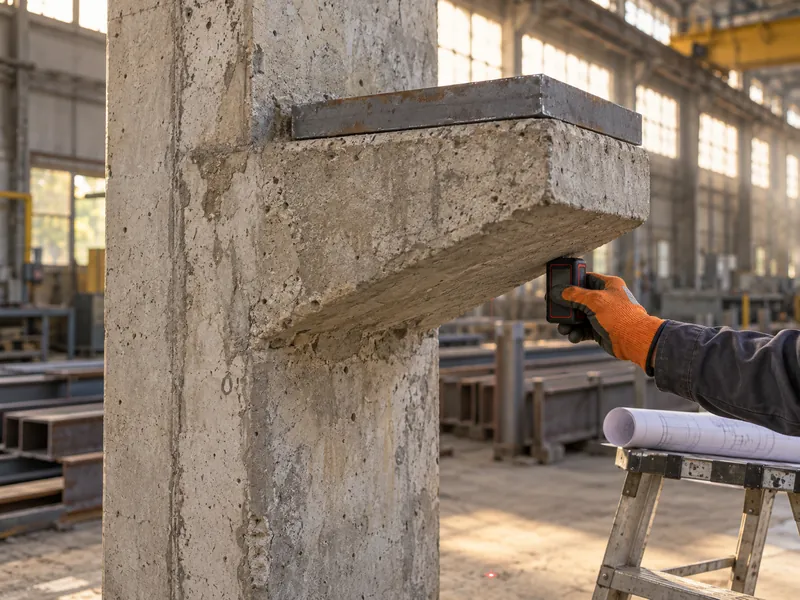
If the existing columns cannot carry the crane, the alternatives are added columns tied back to the building for lateral support, or a fully independent runway structure with its own columns and foundations. Both change the floor plan along the walls, so they feed back into the pick-point map instead of standing as an isolated structural fix.
Load Testing and Inspection Requirements After the Crane Is Installed
Load testing and recurring inspections belong in the crane requirements because the workshop has to allow for them in its access and operating plan. Under the US OSHA crane rule, test loads for new or altered cranes should not exceed 125 percent of the rated load unless the manufacturer recommends otherwise. The same rule separates frequent inspections, at daily to monthly intervals, from periodic inspections at 1 to 12-month intervals. These figures are a US reference. The applicable test and inspection rules depend on the country where the workshop operates.
Testing and inspection cost the workshop space and crane time, so the layout should allow for both. Each test and periodic check needs safe access to the crane and runway. Production should also be able to release the crane without stopping the whole workshop. An access route agreed during design is easier than platforms added later.
Final Planning Order for Workshop Crane Requirements
The order that limits rework runs: map the pick-and-place points, confirm hook approach and lifting height with the crane supplier, place the overhead services, and only then fix span, column spacing and rail elevation in the steel structure workshop design. Capacity and duty class run alongside that sequence from the start, because they set the wheel loads and horizontal forces the frame and foundations must carry. In an existing building, the capacity check of columns, foundations and corbels comes first.
The risk this order targets is the gap between the process layout and the crane’s real reach, not the crane rating. A pick point in a dead zone, or a duct where the trolley needs to pass, is cheap to fix on the layout drawing and costly on site. Put the hook approach limits and the clearance section on the table before the steel frame drawings are released, including where the workshop is designed around a pre engineered metal building architecture.
FAQ
Can an existing steel workshop take an overhead crane if it was not designed for one?
An existing workshop can take an overhead crane only after its original design loads, columns, foundations and any corbels or embedded plates have been checked. Where the columns fall short, the local structural engineer weighs added columns against an independent runway structure.
If the crane rarely lifts its full rated load, does that change the duty class?
Yes, usage can change the class the supplier recommends. Duty class reflects how the crane is used, not its rated capacity alone. Give the crane supplier the expected lifts per shift and typical load weights, and let the class follow from that usage under the classification system the project adopts.
Should the crane runway sit on column brackets or on separate crane columns?
Either can work, and the deciding check is whether the main columns have capacity for the crane’s vertical and horizontal forces. Brackets rely on that capacity. Separate crane columns do not, but they take floor space along the walls. The structural engineer makes the call once the crane supplier provides wheel loads.
How much clearance does an overhead crane need above and beside it?
Clearance depends on the crane configuration and on local regulations, so the crane supplier should confirm it for the specific design. As a US reference, OSHA requires at least 3 inches (about 76 mm) overhead and 2 inches (about 51 mm) laterally from obstructions. Place ducts, lighting, piping and roof members with that envelope in mind.
Further Reading
- OSHA 29 CFR 1910.179 — Overhead and Gantry Cranes — US Occupational Safety and Health Administration / regulation. Supports the clearance, load test and inspection interval references in this article; it is a US rule, so projects in other countries should confirm the local equivalent.
- CMAA Specification No. 70 — Multiple Girder Cranes (2020) — Crane Manufacturers Association of America / specification contents. Shows that crane service classification and the crane inquiry data sheet are separate sections of the specification, which helps owners see what usage information a crane supplier will ask for beyond rated capacity.
- Thorough Examinations and Inspections of Lifting Equipment — UK Health and Safety Executive / regulatory guidance. Gives a non-US example of examination before first use, after on-site assembly and at set intervals, useful when comparing the inspection rules that apply where the workshop operates.