Steel structure workshop design works best when the shop floor is planned first and the frame second. The work zones, the equipment footprint and the way heavy items are lifted decide the span, the clear height and the column layout of a production, assembly or repair steel structure workshop. Planned in that order, those building parameters follow from how work moves through the building. A column grid drawn before the process is mapped can put a column in a forklift aisle. A frame designed without the crane the plant later needs may not be set up to carry it.
The guide below follows that order: work zones and equipment, then span and clear height, then the frame system, the envelope and access items, and finally the line between supplier design and local approval. It does not cover crane load data, member sizing, foundation design or code-specific load values. Those depend on the project location, and the project’s local professionals confirm them.
Steel Workshop Design Begins With Work Zones and Equipment
A zoned floor plan is the first real design input for a steel workshop, because each work area and aisle limits where columns can stand. Published workshop layout guidance starts by dividing the floor by function and keeping clear circulation paths between areas for safety. Before any frame is drawn, the plan should show:
- Equipment envelopes: each machine’s footprint plus the space needed to load, operate and service it.
- Material routes: where raw stock or incoming units enter, where finished or repaired items leave, and the aisles linking them.
- Vehicle and forklift paths, including the door each one uses.
- Assembly, laydown and storage areas that need floor space free of obstructions.
- Support spaces such as tool stores, offices or a mezzanine.
- For repair and maintenance work, the bay where a vehicle or machine is parked while it is opened up, and where removed parts are set down.
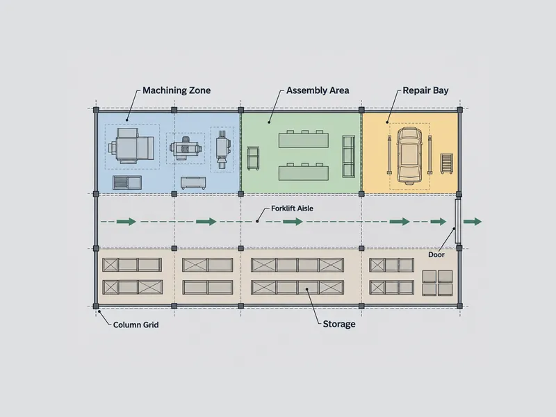
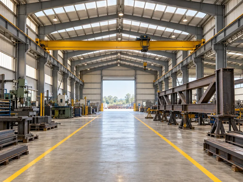
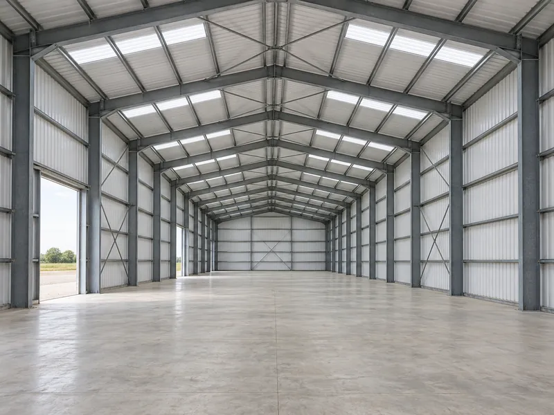
A clear-span frame removes interior columns and gives an unobstructed working area. That matters most when large parts, vehicles or lifting equipment have to cross the full building width. Where the process naturally splits into separate bays, a multi-span layout can work if the interior columns sit on zone boundaries. No column should land in an aisle or under a lifting path. The practical test is to overlay the proposed column grid on the zoned plan and check every column against the equipment envelopes and routes. Exit routes and emergency access still need checking against local regulations.
How Lifting Needs and Equipment Set Span and Clear Height
Span, clear height and column form should be decided together, because the lifting method and the tallest item in the building constrain all three at once. The method below combines published frame guidance with the layout logic above. It is a working approach for production, assembly and repair workshops, not a fixed sequence taken from any single code.
UK steel construction guidance published on steelconstruction.info describes typical single-storey portal frames spanning 15 to 50 m. Symmetric pitched frames are most efficient at roughly 25 to 35 m. The same guidance gives clear heights of 8 to 18 m, measured from floor to the underside of the haunch. Those ranges are a sense check, not a design value. The governing span comes from the zoned layout. The clear height comes from the tallest equipment, the items being lifted and the lifting device itself.
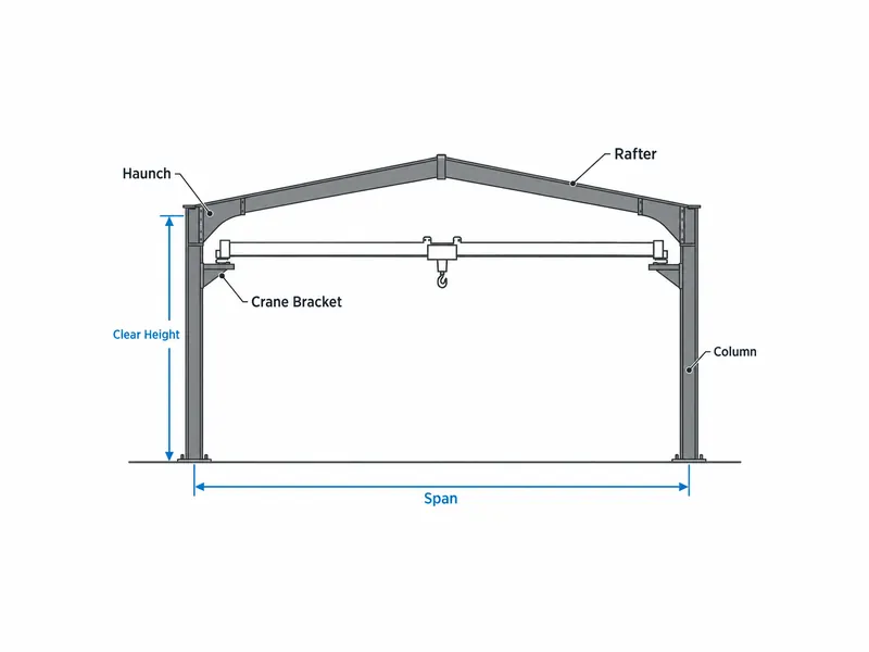
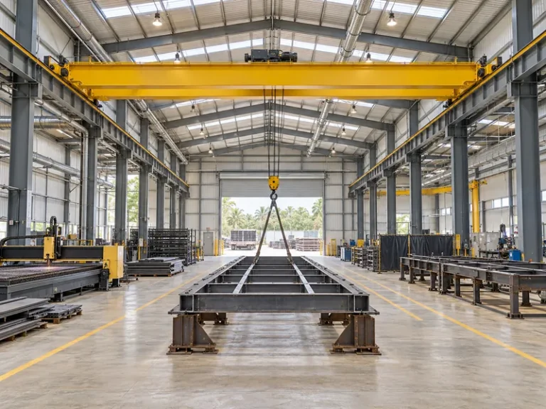
An overhead crane, whether needed now or likely later, belongs in the frame design from the start. The same guidance notes that for crane-carrying frames, the column spread at rail level must be agreed with the client and the crane manufacturer. The crane supplier’s data therefore sits beside the layout as a design input, and those metal building crane requirements need to be settled before the frame is detailed.
Crane capacity also shifts the type of frame. According to steelconstruction.info, brackets fixed to portal frame columns can support travelling cranes of up to roughly 20 tonnes. Where eaves deflection needs limiting, the guidance points to a tie member or rigid column bases. Larger cranes are better suited to a roof truss arrangement, with built-up columns for very heavy loads. A workshop that plans for a light crane today and a heavier one later is choosing a frame type as well as reserving headroom.
Span, clear height and frame type are linked, so a change to any one requirement after the frame is fixed sends the designer back to the others. The table maps each shop-floor requirement to the building parameter it constrains.
| Workshop requirement | Building parameter it constrains | What to check before the frame is fixed |
|---|---|---|
| Work zones, aisles and door routes | Column grid; clear-span or multi-span layout | No column falls in an aisle, door route or lifting path |
| Tallest equipment and lifted items | Clear height to the underside of the haunch or crane | Height covers the item, the lift and the clearance above it |
| Overhead crane, now or planned | Column form, frame type and rail-level geometry | Crane supplier data agreed with the frame designer |
| Future extension | End wall, frame spacing and grid continuation | Extension direction chosen and stated in the brief |
| Site wind, seismic and climate conditions | Frame and cladding design loads | Loads taken from the local code for the site |
Choosing the Frame System for a Steel Structure Workshop
For a single-storey workshop, the main frame options are a rigid portal frame or a truss roof on columns, and the choice follows span and crane duty. Academic design material groups common steel building types into single-storey truss-roof buildings, single-storey rigid portals and medium-rise braced frames. Each type needs lateral bracing so the frame can carry loads without buckling.
For a portal-framed workshop, frame spacing and roof pitch are the next checks. The steelconstruction.info guidance gives typical roof pitches of 5 to 10 degrees, with 6 degrees often adopted, and frames spaced at 6 to 8 m. Each frame line also places a column on the side walls. Door positions and side-wall work zones should be checked against that spacing on the zoned plan.
Crane use frequency matters as well as crane capacity. Steelconstruction.info notes that frequent crane loading usually requires a fatigue assessment. If the crane will run through every shift, state that duty in the brief as one of the steel workshop crane requirements, so the frame designer can scope the checks.
Future extension is a brief item to settle with the frame designer at the first design stage. Three questions cover it: which end wall would be opened, whether new bays should repeat the same span and frame spacing, and whether a crane runway should continue in the same line. The local engineer confirms the answers against the site’s code and ground conditions.
Workshop Envelope, Access and Ventilation Decisions
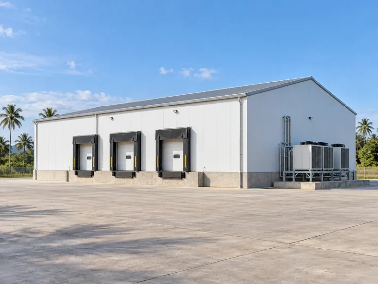
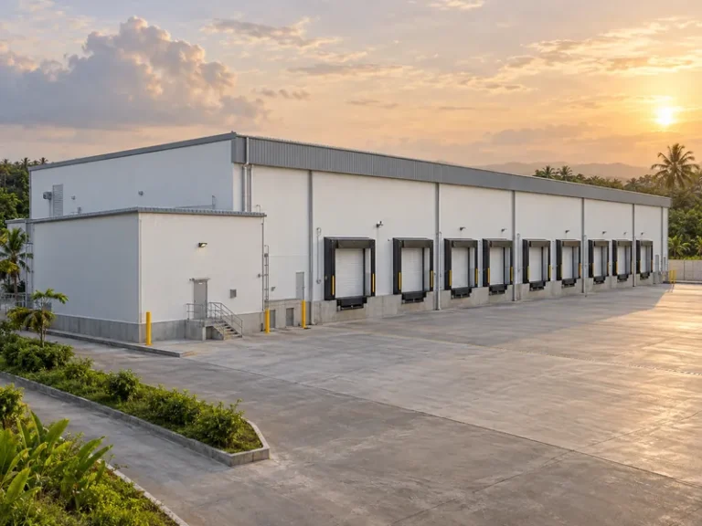
Doors, ventilation and daylight belong in the layout stage, because workshop design guidance lists size and span, door and access systems, ventilation and lighting, and crane systems as linked considerations. For each door, list the largest vehicle, machine or assembly that must pass through and the route it takes inside. Give that list to the frame designer together with the zoned plan.
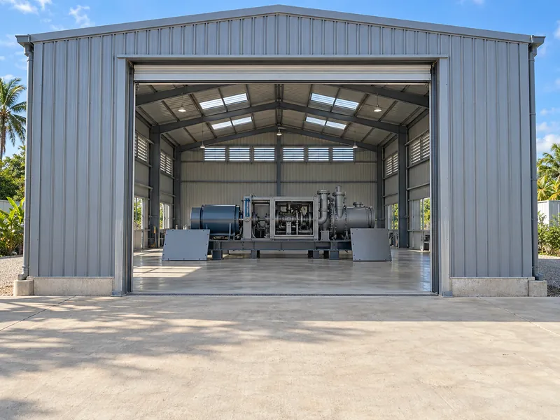
Ventilation needs depend on the processes in the building. Note where welding, grinding, painting or similar work will take place. The local mechanical designer then sets the ventilation and extraction under local occupational and mechanical rules.
Climate and fire items are confirmation points for the local design team. Insulation, cladding and the steel coating system should suit the site’s climate and exposure. Fire separation and protection follow local regulation and the building’s use.
Who Confirms the Final Steel Workshop Design
A supplier’s steel design and the final approved design are not the same thing. The supplier designs the frame to a stated code, and the project’s local professionals confirm the final structural, mechanical, electrical and civil design. Published workshop design briefs and supplier pages reference US, Australian, European and Chinese standards. The code basis should therefore be named at the inquiry stage.
Xinguangzheng, a steel structure manufacturer in Qingdao, China, prepares its pemb design to the code chosen for the site. It describes its buildings as designed to a code, not certified to it. Foundation design and construction stay with the buyer’s local team, which receives the column base reaction data needed for that work.
Whichever supplier prepares the frame, three questions keep the boundary clear. Which code is the frame designed to? Which wind, seismic and other site loads were assumed? Which items does the local engineer still have to check and approve?
Final Check Before the Steel Workshop Layout Is Frozen
Confirm the equipment envelopes and lifting needs before the column grid is frozen. Span, clear height and frame type all follow from those two inputs, and published frame guidance ties crane capacity directly to frame form. The portal frame ranges help test whether a proposal is reasonable. They do not replace the zoned layout, the crane supplier’s data or the local code review.
A workshop frame argued from the zoned plan, the tallest lifted item and the crane decision gives the local engineer a brief that can be checked line by line.
FAQ
How do equipment layout and work zones affect the span of a steel workshop?
Equipment layout and work zones decide which aisles, door routes and lifting paths the frame has to keep clear of columns. A clear-span frame suits layouts where large items or vehicles cross the full width. A multi-span frame can work when columns can sit on zone boundaries. Overlaying the column grid on the zoned plan shows which option fits.
Should a fabrication workshop with an overhead crane be clear span or multi-span?
Clear span suits a crane that must serve the full width, while a multi-span layout can suit a process split into separate bays. The choice depends on the crane’s coverage, the column positions the process can accept and the crane supplier’s data. Frame type also changes with crane capacity, so decide it with the frame designer and the crane manufacturer together.
What should be decided now if an overhead crane may be added later?
Treat a future crane as a current design input: its likely capacity, coverage and the clear height it needs. Published portal frame guidance links crane capacity to frame form, with column brackets suiting lighter cranes and truss roofs or built-up columns suiting heavier ones. Frame design also has to settle the column spread at rail level with the crane manufacturer.
How can a steel workshop be planned for future extension?
Settle the extension direction, the end wall to be opened and the frame spacing at the first design stage. State whether new bays should repeat the original span and whether any crane runway should continue in line. The local engineer should still confirm the extension against the site’s current code and foundation conditions.
Further Reading
- Portal frames — steelconstruction.info, UK steel construction technical resource. Supports the typical span, clear height, roof pitch, frame spacing and crane-bracket guidance cited above; written for UK and Eurocode practice, so project values still come from the local code.
- Design of a workshop in steel — Cyprus University of Technology repository, academic thesis record. Supports the classification of single-storey truss, rigid portal and braced-frame building types; the worked design follows BS 5950, so its values need checking against the local code.