Metal building purlins are the light roof members that collect load from the roof panels and deliver it to the main frames. Every pound of roof dead load, snow, maintenance traffic and wind uplift passes through them before it reaches the columns. In a rigid frame steel building, the rafters set where purlins are supported, while the purlins set how far the roof sheets have to span. Getting purlins right is less about picking a profile and more about reading three things together: the section, the way it laps across the frames, and the restraint the roof panels give it.
The sections below cover how purlins carry load, what decides their span and spacing, and which design assumptions a buyer or project engineer should confirm. They do not cover full roof system selection, coating system design or pricing. Final structural design remains the responsibility of the project’s local engineer of record.
What Metal Building Purlins Carry in the Roof Load Path
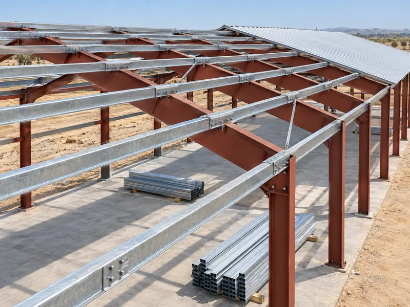
Purlins are secondary framing: they run across the rafters, support the roof sheeting, and transfer roof loads to the primary frame. Gravity loads push the panels down onto the purlins. Wind uplift pulls the panels and purlins away from the frame, so a purlin line has to work in both directions over the life of the building.
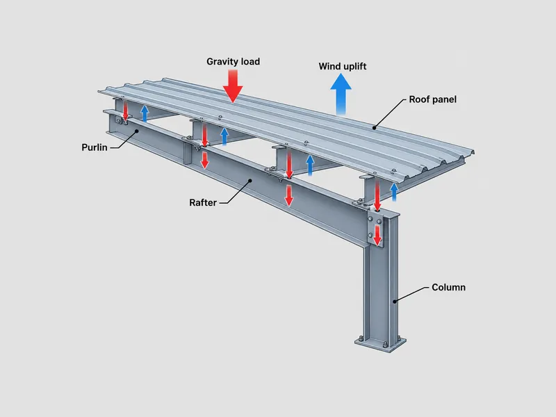
Within the wider secondary framing package, purlins sit alongside girts, eave struts, flange braces, base members and clips. Girts do the same job on the walls, collecting wind pressure from the wall panels and carrying it to the columns. The eave strut sits at the junction of roof and wall and works partly as both, which is why designers usually detail it as a separate component. Industrial buildings need the roof and wall members identified by their separate roles. A drawing review for workshops should keep that distinction clear.
Pre fabricated steel structures use the purlins and girts described here where that envelope system is specified. The same member distinction applies to aircraft hangars.
For anyone reviewing a pre engineered metal building structure, purlin members are not interchangeable stock items. Their size, thickness and lap layout come out of the roof loads and frame spacing of one specific building. That makes the purlin drawing as project-specific as the frame drawing.
PEMB Purlins: Z Sections, C Sections and Lap Continuity
Choosing between Z and C purlins in a PEMB is really a choice between a continuous roof system and a simple-span one. Both are cold-formed steel sections, but Z purlins can nest into each other over a frame line, so overlapping Z sections act as continuous beams across several bays. C sections have squared, independent flanges that do not nest the same way. They are more often used for single spans, wall openings, door jambs and headers. Their wall counterparts are explained in steel building girts. The roof-to-wall member at the eave is described in metal building eave strut.
Continuity is what makes lapped Z purlins a practical option for roofs that run across several bays. A continuous purlin line shares bending between spans, so the interior spans work more efficiently than a row of separate simple beams. The trade-off is that continuity moves the critical design zone. Over each frame line, the lap region sees high negative bending and shear. Under uplift, it also has a compressed bottom flange with limited bracing.
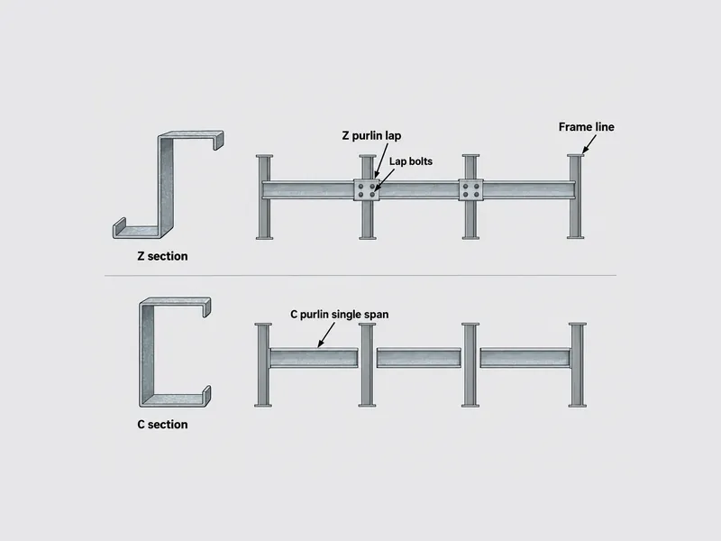
The lap region is where purlin problems tend to appear. A 2024 analysis published in STRUCTURE magazine by Tim Lane and Cris Moen identified bottom flange buckling near the frame-line laps as a common failure mode in metal building purlins. The authors also noted that manufacturers historically tested simply supported single-span purlins and extrapolated the results to continuous spans. That approach can miss strength limit states near the laps.
For a reader comparing two quotes, the useful question is not “Z or C?” but “single span or lapped, and how were the laps checked?” A Z purlin offered without a clear lap length and lap bolt layout is only half specified, because lap detailing sets the strength of the line.
Metal Building Roof Purlins: What Sets Span and Spacing
The span of metal building roof purlins is set by the frame bay spacing, while purlin spacing is set by what the roof panels can span and the design loads they carry. Wider bays mean longer purlin spans and, usually, deeper or thicker sections. Wider purlin spacing means fewer purlin lines but a heavier load per line and a longer span for the roof sheet.
Published North American examples often show purlins at about 5 ft on center, and the same examples commonly use cold-formed steel with a nominal yield strength of 55 ksi. Treat those numbers as illustrations of typical practice, not as a starting design. On a real project, spacing follows from the panel’s load tables, the governing snow, live and wind loads, and the purlin capacity. Steel grades in a given market follow local supply and code.
End spans can need a heavier purlin than interior spans. In both the STRUCTURE magazine case study and an AISI-funded worked example of a four-span standing seam roof, the end-span purlins were thicker than the interior ones. A continuous line does not receive the same help from its neighbors at its ends. A layout drawing that shows one uniform section through every bay is therefore worth querying with the designer.
Gravity and uplift load cases control different parts of the purlin design. Gravity loads from dead load, roof live load and snow can govern where the code requires significant snow, including drift or unbalanced snow near steps and ridges. Wind uplift can govern instead on light roofs at exposed or cyclone-prone sites. Uplift loads the purlin in the opposite direction, which changes which flange is in compression.
How the Roof Panel Changes What a Purlin Can Carry
The same purlin section can carry different loads depending on how the roof panel attaches, because the panel is part of the purlin’s bracing. A through-fastened panel screwed directly to the top flange restrains that flange against sideways movement and twisting. A standing seam roof sits on clips that let the panel slide with thermal movement. Those clips give the purlin less, and different, restraint.
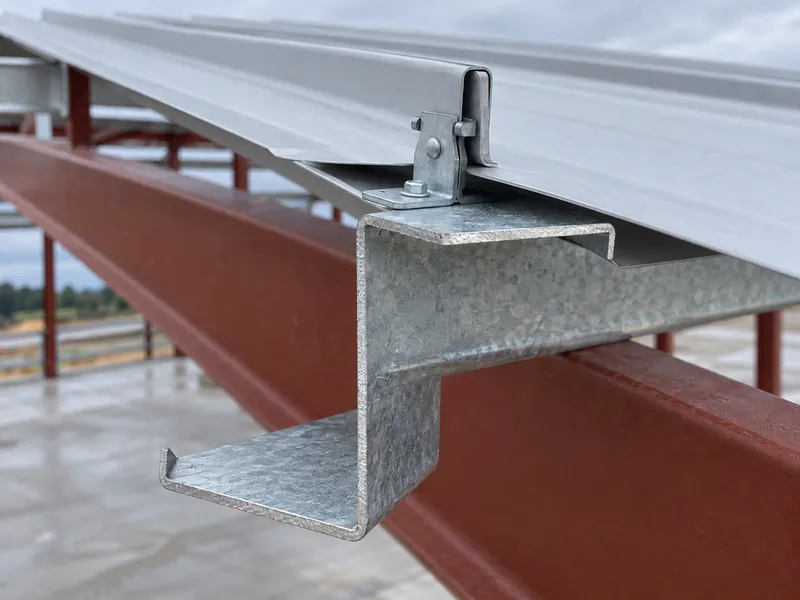
An AISI-funded worked example by Cris Moen of a four-span Z-purlin line under a standing seam roof shows how much this matters. In that single example, the lateral stiffness provided by the clips substantially increased the purlin line’s strength, while rotational stiffness mattered less. Under gravity load, distortional buckling in the exterior spans controlled. Under uplift, combined bending and torsion at the first interior support, in the lap region, controlled. The numbers belong to that one example only, but the pattern explains why the roof type has to be known before the purlin design is final.
Engineers writing in STRUCTURE magazine in 2024 pointed out that the AISI S100-16 edition used in their work includes methods for combined actions and partial bracing from attached roof panels. They also noted that the 1989 standard had not yet incorporated distortional buckling. For an export project, consistency matters more than a specific edition. The purlin calculation should state which cold-formed steel standard and edition it follows, and the project’s local engineer should confirm that the building’s jurisdiction accepts it.
Purlin design and metal roofing systems meet at this restraint question. Switching from a screw-down sheet to a standing seam roof late in a project, or reroofing an existing building with a different panel, changes the restraint the original purlin design relied on. In that case, repeat the purlin check instead of assuming the old one still holds.
Metal Building Purlin Bracing and Flange Restraint
Metal building purlin bracing exists because a thin cold-formed section is stiff in its own plane but weak sideways and in twist. Under load, an unrestrained Z or C purlin can twist and buckle sideways before it reaches its full in-plane bending strength. Bracing and restraint keep the compression flange in position so the section can develop the capacity the designer assumed.
Which flange needs help depends on the load direction. Under gravity, the top flange is in compression across most of the span, and the roof panel partly restrains it. Under wind uplift, the bottom flange goes into compression between frames, and the roof panel does little to hold it. Uplift is therefore often where unbraced or lightly braced purlins are most exposed. Near the frame lines, the bottom flange is also in compression under gravity, which is part of why the lap zone is sensitive. The wider bolt and screw families are distinguished in metal building fasteners; the project drawings still set the lap connection.
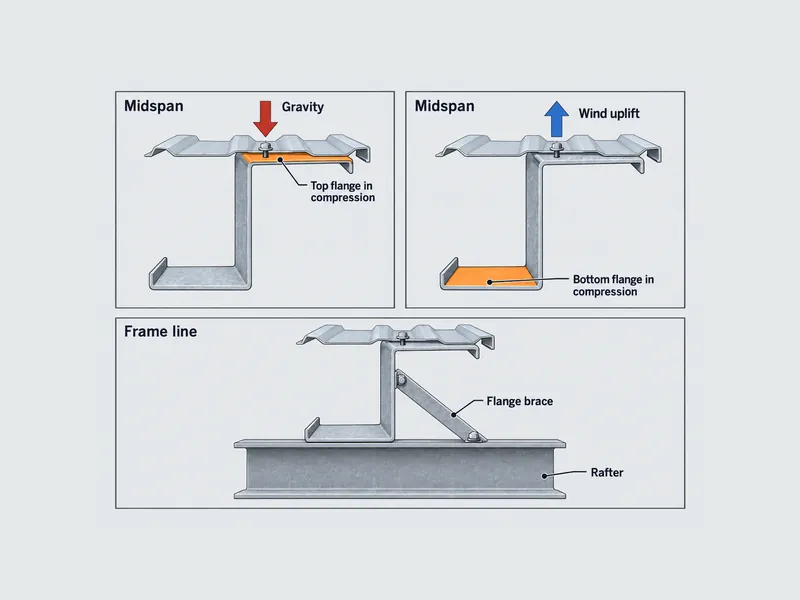
Secondary framing packages typically include flange braces and other restraint members alongside the purlins. The type, number and location of those braces are outputs of the design, not standard accessories. A bracing layout drawn for a through-fastened roof may not be valid for a standing seam roof, and a layout drawn for gravity alone may not cover the uplift case. If the erection drawings and the calculation show bracing in different locations, ask the designer or engineer of record to reconcile them in writing before erection.
Purlin Design Assumptions to Confirm Before Approval
The most useful review a buyer or project engineer can do on a purlin design is to confirm the assumptions behind it, not to recheck the arithmetic. Each item below connects to the load path described above, and the supplier’s calculation and drawings should answer it:
- Span and end bays: the frame bay spacing used, and whether end spans use a heavier section or thickness than interior spans.
- Spacing basis: the purlin spacing on the drawing and the roof panel load table and design loads it was derived from.
- Laps: lap length at each frame line, lap bolt layout, and whether the lap regions were checked for combined bending and shear.
- Restraint assumptions: the roof panel type and fastening method assumed in the calculation, and whether it matches the panel actually supplied.
- Bracing for uplift: what restrains the bottom flange under wind uplift, and where flange braces or other restraint members are placed.
- Code and coating: the cold-formed steel design standard and edition used, and the purlin coating (galvanized or primer-only) for the building’s exposure.
Coating belongs on this list only as a condition to confirm. Galvanized purlins are a common option for secondary framing. Whether a given finish suits a humid, coastal or chemically aggressive site is a matter of corrosion protection for steel buildings, settled in the project’s coating specification.
Existing buildings need the same discipline when new loads arrive. Solar arrays, hung ceilings, ductwork and sprinkler mains all hang their weight on purlins sized for the original roof. In the 1989 building analyzed in the STRUCTURE magazine article, the authors calculated that the original purlins carried a design demand about 1.5 times their predicted allowable load. They argued that informal rules allowing small load increases without calculation should have engineering calculations behind them. Before adding load to an existing roof, have an engineer check the purlin lines, including the laps.
Purlin Sections Are Only Half of the Purlin Design
A purlin layout makes sense only when the section, the lap continuity and the roof restraint are read together. A Z purlin in a continuous line behaves differently from the same section in a single span, and the same lapped line can carry different loads under a screw-down roof and a standing seam roof. The profile name and the spacing figure are what most readers look at first. In practice, the lap details and the restraint assumptions decide how much load the line can safely carry, so those are the first items to confirm on any metal building purlin drawing.
FAQ
Should Z purlins or C purlins be used on a multi-bay metal building roof?
Z purlins are often chosen for multi-bay roofs because they can lap over the frames and act as continuous beams. C purlins more often suit single spans, wall openings and framed details where continuity is not needed. Either way, the designer has to check the lap or connection design as part of the purlin line.
How is purlin spacing decided when the roof uses standing seam panels?
Purlin spacing under standing seam panels is decided by the panel’s span capacity, the design loads and the purlin strength with the restraint the clips actually provide. Clip-attached roofs generally give purlins less restraint than through-fastened sheets. The designer should check spacing and section for that roof type instead of copying them from a screw-down design.
Do metal building purlins still need bracing once the roof sheets are fastened?
Fastened roof sheets help restrain the top flange, but purlins generally still need designed bracing or flange restraint, especially for wind uplift, when the bottom flange is in compression. The bracing layout should come from the purlin calculation for the specific roof type and load cases.
Can solar panels or a hung ceiling be added to an existing metal building without checking the purlins?
Adding solar panels or a hung ceiling without checking the purlins is risky, because purlins are sized for the loads in the original design. Published analysis of one existing metal building found its original purlins beyond their calculated allowable load. The purlin lines and their laps need an engineering check before any new load goes on.
Why do purlins tend to fail near the laps over the main frames?
Purlins tend to fail near the laps because that zone combines high bending, shear and a compressed bottom flange with limited bracing. The 2024 STRUCTURE magazine analysis points to bottom flange buckling at those laps. Continuous purlin design therefore needs explicit lap checks instead of results extrapolated from single-span tests.
Further Reading
- What About the Purlins? (STRUCTURE magazine, 2024) — Industry journal. Case study of an existing metal building roof showing lap-region failure modes and purlin overstress; North American codes and a single building, so values are not general design figures.
- Four-Span Metal Building Z-Purlin Line Supporting a Standing Seam Roof (AISI-funded worked example) — Technical worked example. Shows how clip restraint and load direction change the controlling limit state; results apply to that one example only.