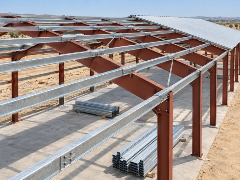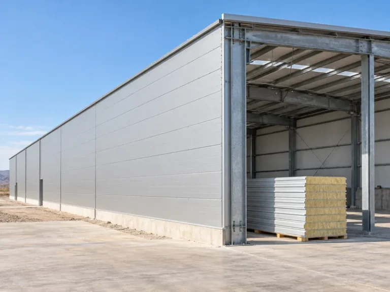
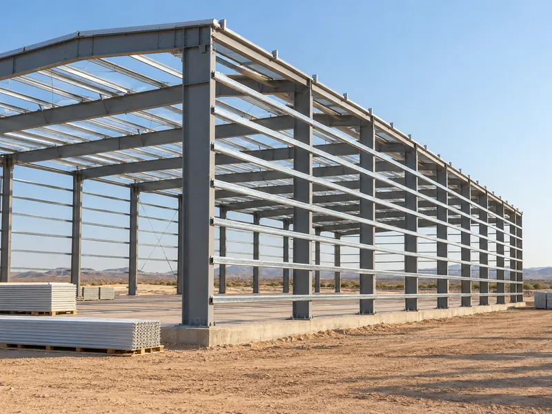
Metal building girts are the horizontal wall members that span between columns, support the wall panels and carry wind on the wall back to the frame. In a rigid frame metal building, girts run across the sidewall and endwall columns, while purlins do the matching job on the roof. To read a girt on a drawing, you need three things: what the member does, where it sits relative to the column, and where openings and edge members interrupt the girt line.
Girts belong to the secondary framing, one of the components of a metal building that is engineered together with the primary frame. Girt sizing calculations, bracing design and prices are outside the scope of this article; those belong to the building’s structural design and the project engineer. Where wall bracing uses a V pattern, the guide to V bracing steel structure follows the forces through that layout.
What Metal Building Wall Girts Do in the Wall
Wind load on the wall is the main thing a girt resists, and lateral support for the wall panels comes with the same job. The girt rows collect wind pressure from the cladding and deliver it to the columns at each frame line. That makes the girt the link between the building skin and the frame. Because the girt sits on that load path, the design wind criteria shown in the building’s drawings or calculations are the first variable behind any girt layout. Those criteria should match the site.
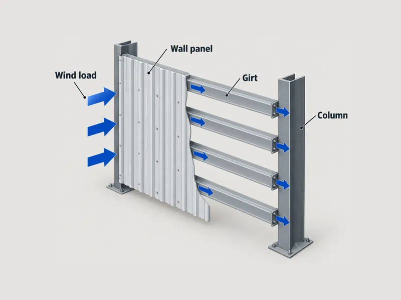
Girts and purlins differ by position and load, not by concept. Girts work in the walls and resist mainly lateral wind, while metal building purlins sit in the roof and carry roof loads to the rafters. Together, metal building purlins and girts form the grid that ties the building envelope to the primary frame and gives panels, insulation and accessories a place to fasten. Girts are also known as sheeting rails, and the function is the same under either name.
Z Girt Framing and C-Section Girts
Most girts in metal building systems are cold-formed steel, roll-formed into a C or Z profile. Both shapes appear in supplier specifications. The building designer sets the section on a given wall from the supplier’s section range; the buyer does not pick it from a catalog. The section mark on each girt row tells you which shape and size the design calls for.
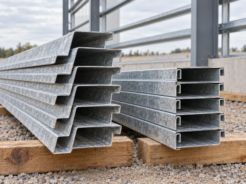
Z girt framing depends closely on how the girt meets the column. Suppliers offer Z girts in a bypass configuration that laps past the outside face of the column, or in a flush configuration that sits in line with the column. Z sections are widely used for wall girts, but the drawing, not a general rule, confirms which shape a particular wall uses.
C sections often appear at the edges of the wall system as well as in girt rows. In some secondary framing systems, plain C channels serve as jambs and headers for framed openings, and lipped C sections are used as sill girts above open walls. A single wall elevation can therefore show both C and Z members, each doing a different job.
The supplier’s design fixes section depth, steel thickness and coating; a generic chart does not. Published supplier ranges vary from company to company and are usually stated in US inches and gauge numbers. Those figures may not map directly onto the section tables used when a project is designed in metric units. For coating, galvanizing or a shop primer are the finishes commonly listed for girts. Which one a wall needs follows from its exposure, so the girt coating should be settled with the project’s wider corrosion protection for steel buildings, not left at a default.
Bypass vs Flush PEMB Girts at the Column
Bypass and flush describe where PEMB girts sit relative to the column. A bypass girt runs across the outside face of the columns and laps at each column line. The girt line continues past the frame, and the cladding sits outboard of the columns. A flush girt is framed between the column flanges on clips, needs no laps and keeps the inside face of the wall flat. Flush placement is therefore the option to ask about when a flat interior wall face matters for liners or interior finishes.
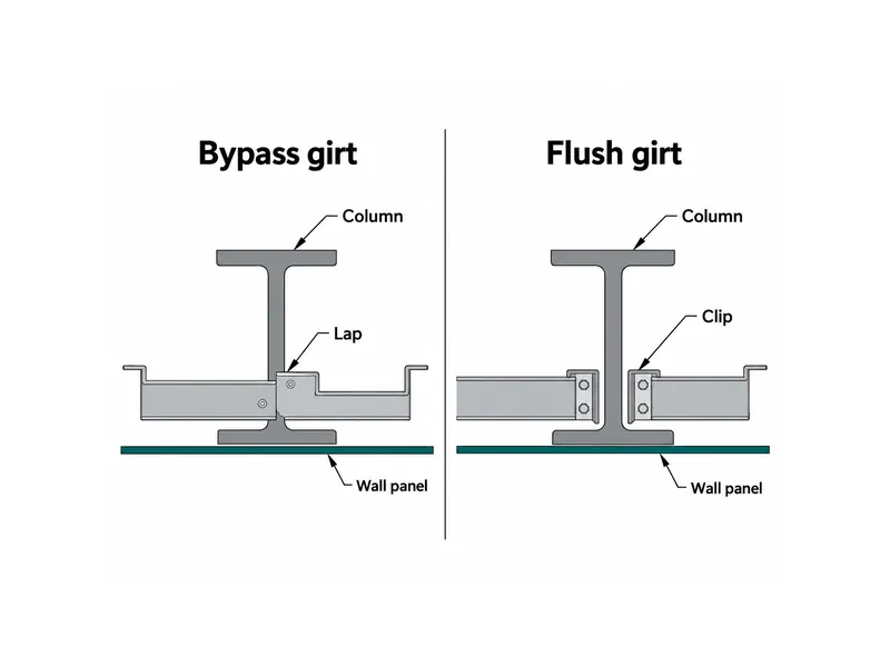
The two placements also read differently on drawings and quantity lists. Bypass walls carry a lap allowance at every column line, while flush walls show clip connections at each column instead of laps. When two quotations assume different placements, the girt quantity and the interior wall condition both change, so confirm which placement each supplier priced before comparing totals. The building’s structural design decides whether a specific frame can take flush girts, and the connection details in either case.
Where Girt Rows Meet Openings, Eaves and the Base
Every door, window and louver cuts through the girt rows it crosses. Jamb and header members then pick up the cut ends and support the panels around the opening. A wall elevation that shows an overhead door but not its jambs and header is incomplete, because the loads the missing girt sections would have carried must go somewhere.
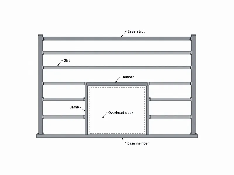
Opening width is the variable that changes the girt layout locally. A wide door removes a section of several girt rows at once. On a quantity takeoff, the interrupted girt length comes off and the jamb and header framing goes back on. Check on each elevation that the girt rows stop at the jambs and that every opening has its own framing members marked.
At the top and bottom of the wall, the girt rows hand over to other secondary members. A secondary framing system typically includes base members, girts, eave struts, purlins, flange braces, gable angles and connection clips. The eave strut and base member are separate items from the girt rows. Counting them as girts on a takeoff, or assuming one supply line covers all of them, is a scope gap worth closing early. The separate roof-to-wall member is discussed in our eave strut metal building guide.
How Girt Size, Spacing and Deflection Are Set
Girt size and spacing come out of the engineered building design, not from a rule of thumb. On a pre-engineered building, the secondary framing is usually designed and supplied as part of the building package. The girt layout should therefore be readable from the supplier’s drawing set, for example the erection drawings or wall framing elevations. The responsible engineer for the project’s location confirms the final structural design. A prefabricated steel structure with girt-framed walls needs a drawing-based check of the girt layout. Take the actual wall arrangement for industrial buildings from those drawings.
Large openings are part of the layout to review on aircraft hangars. Check the specified girt runs around the openings in workshops as well.
Deflection under wind is one of the checks behind that layout. The International Building Code deflection table appears as Table 1604.3 in a 2007 Florida Building Code supplement. In that table, secondary wall members supporting formed metal siding are limited to span/90 under design wind load. The same table allows the wind load for this deflection check to be taken as 0.7 times the components-and-cladding load.
Wall finish changes which limit applies. The same IBC table sets span/240 for exterior walls with brittle finishes and span/120 for walls with flexible finishes, both tighter than the span/90 allowed for girts behind formed metal siding. A wall clad in single-skin metal panel sheets falls under the formed-metal-siding line. Adding a brittle finish to that wall is a design change that should go back to the engineer, not a fit-out detail.
The IBC limits come from one code family and one edition. Projects in jurisdictions that do not use the IBC, or that use a different edition, follow their own deflection rules. Confirm which limit and which wind criteria the girt design was checked against. A higher design wind load increases girt deflection for the same section and spacing, which is why the wind basis on the drawings has to match the actual site.
Reading Girts on the Wall Framing Drawings
The wall framing drawings let you check each girt question above before accepting a design or comparing two quotations. Missing items are questions for the supplier, not grounds for the buyer to redesign the wall:
- Section marks for every girt row, showing C or Z shape, and whether sidewalls and endwalls differ.
- Girt row spacing on each wall elevation, together with the design wind criteria and code the layout was checked against.
- Placement at the columns: bypass with lap locations shown, or flush with clip connections at each column.
- Opening framing: jambs and headers drawn at every door, window and louver, with girt rows stopping at the jambs.
- Edge members: eave strut and base member shown as separate marks, with their supply scope stated.
- Coating: galvanized or primed girts, matched to the exposure set in the corrosion protection specification.
The six points describe what the wall drawings should show; they do not replace the structural calculations. The project calculations and the responsible local engineer still settle whether the girts work under the site’s wind loads and the project’s own code. Where an answer is missing, ask the supplier for it in writing so the gap is closed before fabrication, not on site.
What Girt Placement Tells You About the Wall
Think of a girt as the wind-carrying layer between the wall cladding and the columns. Its placement at the column shapes the rest of the wall. Placement decides whether girt lines lap past the frame or stop at each column on clips, whether the inside face is flat, and how girt quantities are counted. The easy misreading is to treat girts as a generic line item, when section, spacing and deflection all trace back to the building’s wind design and the code the project follows.
A wall elevation is ready to accept only when it shows the girt placement, the jambs and headers at each opening, and the eave strut and base member as their own marks.
FAQ
What are girts in a steel building?
Girts are horizontal wall members that span between the columns of a steel building, support the wall panels and resist wind load on the wall. In metal building systems they are usually cold-formed C or Z sections. The roof counterpart of a girt is the purlin.
Should I use bypass or flush girts if I want a flat inside wall face?
Flush girts keep the inside wall face flat because they sit between the column flanges on clips. Bypass girts run past the outside face of the columns and lap at each column line. Whether a particular frame can take flush girts is a structural design decision, so ask the supplier to show it on the drawings.
Are girts and purlins the same section, just used in walls instead of the roof?
Girts and purlins are both cold-formed secondary members, often from the same C and Z section family, but each is designed for its own position. Girts carry mainly lateral wind on the wall, while purlins carry roof loads to the rafters. A matching shape does not make them interchangeable, because size and spacing come from different design checks.
Are metal building girts C or Z sections?
Metal building girts come in both shapes. Z sections are widely used for the girt rows themselves. C sections often frame the edges of the wall, such as jambs and headers at openings or sill girts above open walls. The section mark on each girt row of the wall framing drawings shows which shape the design actually calls for.
How do girts change around a large overhead door opening?
Girt rows stop at a large overhead door, and jamb and header framing picks up the cut ends and supports the panels around the opening. The wider the door, the more girt rows it interrupts. Check that the wall elevation shows the jambs and header for each door, not just the door opening itself.
Who decides girt spacing on a pre-engineered metal building?
Girt spacing comes from the engineered building design, usually prepared by the building supplier and based on the design wind criteria and the code the building is checked against. The supplier’s wall framing drawings should show that spacing. For projects outside IBC jurisdictions, the local engineer of record confirms that the layout meets the local code.
Do IBC girt deflection limits apply to projects outside the United States?
Only where the project’s jurisdiction has adopted the IBC, and then only in the edition it uses. The span/90 limit for girts behind formed metal siding comes from one IBC table edition. Projects under other building codes follow their own deflection rules, so ask which code and wind criteria the girt design was checked against.
Further Reading
- IBC Table 1604.3 Deflection Limits (Florida Building Code 2007 supplement) — Florida Building Commission, code table. Source of the span/90 limit for secondary wall members supporting formed metal siding and the span/240 and span/120 wall-finish limits; it reflects one 2007-era edition, so check the edition your jurisdiction adopts.
- A guide to changes in the specification of cold formed galvanized steel purlins and girts — Metal Building Products Manufacturers Association, via the Australian Steel Institute eLibrary. Library record of a specification guide on galvanized cold-formed girts and purlins; it is a historic 1992 brochure with member-only access, useful as a pointer to how girt coating and specification are documented outside the US.